I agree with MDAR’s analysis:
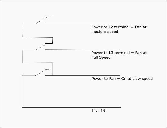
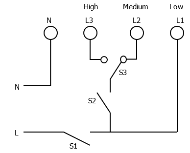
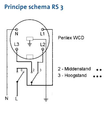
L1 = slow
L1 + L2 = medium
L1 + L3 = high
This means we can see L1 as a kind of on/off (or slow/off). If we additionally connect L2 OR L3, we change the speed accordingly to resp. medium or high.
I would suggest using a VMB2BLE shutter module as a changeover relay (or, I you have some patience, the VMB1BLS, available soon). The VMB2BLE relays are hardware designed to only allow the “up” or “down” to be active at a given moment. Because this is hardware built-in, it’s very secure. By putting the “total timeout” value to “continuous”, it will act as a changeover relay.
The general setup would then be:
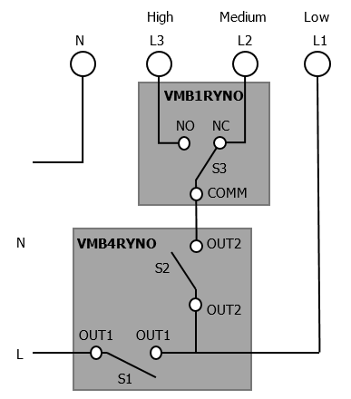
- connect L1 through a VMB4RYxx relay (which would be on under normal operation, but when needed will allow you to power down the ventilation, like an alarm stop)
- connect L2 and L3 to the “up” resp. “down” of a VMB2BLE shutter module. So “up” will then correspond to your medium speed, and “down” to your high speed.
Now the buttons to control the ventilation… This is a bit “out of the box” thinking, so what I’m going to explain may seem a bit complicated or strange, but it seems to work perfectly in my test setup. We will also need a virtual relay.
In Velbuslink, make the following actions:
(if the image doesn’t show, try again in an hour or so while it syncs on our network)
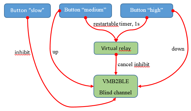
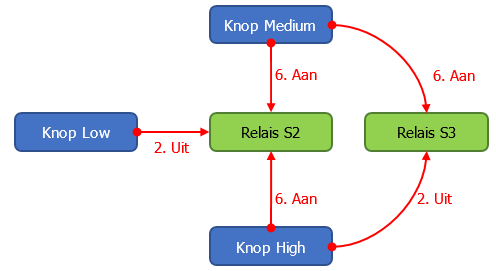
- button “slow” → blind channel: inhibit (action nr.65)
- button “medium” → virtual relay: restartable timer 1s (15)
- button “high” → virtual relay: restartable timer 1s (15)
- virtual relay → blind channel: cancel inhibit (67)
- button “medium” → blind channel: “direct up” (2)
- button “medium” → blind channel: “direct down” (5)
Pressing the “slow” button inhibits the medium/high relays and thus makes the ventilation fall back to slow speed. Pressing the “medium” or “high” button cancels this inhibition (through an intermediary virtual relay) and switches the medium resp. high speed on. Pressing “slow” again, falls back to slow speed by inhibiting again the two higher speeds.
Note that the L1 connection does not come into play here, and is expected to be always on. The three buttons above only interact with the L2/L3 connections.
The intermediary virtual relay in my setup is necessary (or at least higly recommended) because it is not good practice to define two different actions between the same initiator/subject couple, as this can give unforeseen results.
Now if you want to combine the three buttons in one single button (which toggles speeds slow-medium-high-slow-etc by consecutively pressing it), you can use the “multi” mode, available on most input modules (except VMBGPOD).
Lastly, programming will then consist of simply activating the “slow”, “medium” and “high” buttons as needed.
Does this make any sense to you? I think it should work, but it’s more difficult to explain than to do. In case I would have missed something, please complete/comment.


