try to use caps 
1 Like
Oh yeah, my life got easier when I was introduced to bootlace ferrule grimps
But I’ve had Cat5 cores fracture in them too.
But I’ve had Cat5 cores fracture in them too.
I always try to be shure to shrink them partly on the isolation of the wire, this way you’ll you a kind of strain relief.
I discovered that terminators were set in many places. In almost all VMBPIRC, … I removed, I hope all of them, and I have now only 2 terminators: one in the electric cabinet and one in a OLED (at the end of the bus leg on the first floor).
But now it does not connect again (or it takes a very long time…).
I have one long bus leg for the 1st floor (where the terminator is set), one bus leg for the ground floor, one bus leg for the basement and a a bus leg in the attic.
The voltage at the OLED where the terminator is set is 12.3V
The voltage at the last module of the bus leg for the ground floor is 14.7.
However, the resistance are not at all as expected::
in the electric cabinet: 40 ohm
At the end of the bus let of the ground floor: 40 ohm
At the OLED where the terminator is set on the first floor: no stable value… oscillating bewteen 0 and 180 ohm.
What can be the problem for the resistance?
Thanks
Christophe
Hi Christophe,
It sounds like you’ve got more than “just a loop” ![]()
May I make an ‘extreme’ suggestion?
(Given that you didn’t originally wire up the system, so can’t be absolutely certain of what goes where)
And that you say —
In this situation, where you’ve been looking at it for a number of days / weeks, I would suggest the following ;
Deliberately break your installation onto small sections and get a single section working perfectly, before moving on to the next section.
There are many benefits from this approach.
-
You can be absolutely sure that each section is perfect
-
An opportunity to label every cable in your cabinet
-
Opportunity to check end of line voltages and impedance, knowing that it’s only that section you’re measuring. – aim for 15v at the end of line and no more than 17.5v at the PSU
I would start by disconnecting everything external of your cabinet and check that first.
Good luck,
Stuart
Yes, I think also that it’s the only possibility. I’ll do it (as soon as possible, I can explain you in private why I cannot do it immediately).
For the impedance, do you have an idea what might be the cause?
And why the voltage decreases from 15V in the cabinet to 12 at the end of the line? Wires wrongly connected?
For the power supply, I’ve noticed that there are correctly 3 units… 4A, 15V… but not Velbus power supplies … Might it be a problem? Or any power supply works?
In addition to all this, something really strange:
When I connect in the VelbusLink without changing the size of the screen (I let it at the size it is when it opens by default in Windows), it works very fast. If I maximise the VelbusLink on the screen, the monitoring window on the top right seems to be frozen/slow, modules seems not to respond… and it takes 1 hour to connect… I know it sounds really strange… but that’s what it does on my computer (which is working fine for the rest, Windows 10).
Thanks
Hi
I’m sure there is a really good reason why ![]()
Could it be that you are kept busy else where?
Or that you are in fact a world famous deep sea diver and are only on land for a few days a year?
That might be a really simple answer…
The cores of the cable that have been installed are too thin and you are suffering volt drop along the run?
Try raising the voltage in the cabinet to 17.5v and see what the end of line voltage looks like.
Umm…
So you have 3 seperate power supplies in your system, each supplying a different leg of your installation?
PLEASE tell us that the +Ve of each PSU is isolated from the others?
The easy way to tell is to power down 2 of them and see if you lose power to 2/3 of your installation.
The golden rule is…
You may use multiple PSU, but ONLY if the +Ve is seperate.
You should only connect
0VE, Data High and Data Low across everything in your network.
This PDF has examples of multiple PSU deployment - Basic_Wiring_plan_V1.5.pdf
That sounds like an issue with Windows 10, rather than the Velbus network.
Hello,
On that leg where there is a voltage drop, only EIB cable is used.
I will verify the connections of the PSU.
I used the application the Velbus website to determine how many PSU are necessary with my modules. And it said 3. That’s why I have 3. One would be simpler for the cabling, but would not be enough, right?
Thanks
1 Like
A voltage drop is expected on (semi-)long cables. Since you’re still measuring 12V it will be fine if there are only push button modules at that end.
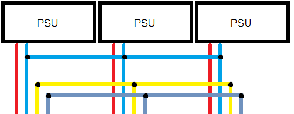
By PSU’s, MDAR means that only the ‘-’ of each of those should be connected to each other, not the ‘+’.
Consider this small diagram:
+: red
-: blue
H: yellow
L: grey
1 Like