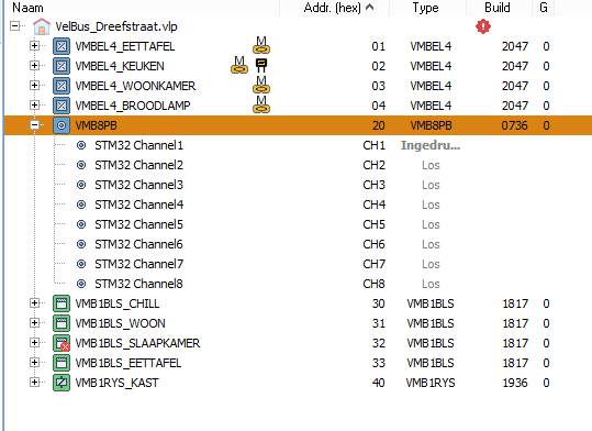
Made great progress over the last days. Now have a “STM32” based VMB8PB module working.
The STM32 responds to the “scan” request with the module type.
Also the status request messages are answered.
Also all comands to read / write the memory have been implemented (although it now writes the RAM of the STM, so everthing is lost on power down). Have to check how to write the EEPROM of the STM32.
When I press the button, the corresponding channel message is send.
Memory map of the VMB8PB is extremely simple, so that helped a lot.
Cleaning up code and then see if I can made a motion sensor input. Much more complicated as there are a lot more settings to handle.
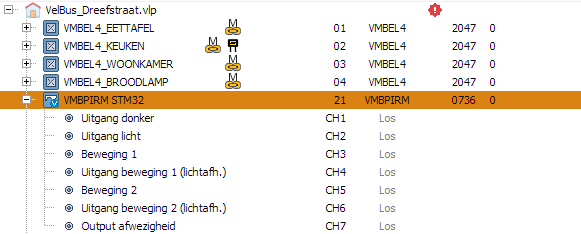
Dont know if any one is interested, but made another huge step.
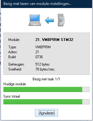
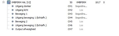
Made a VMBPIRM module and now can write & read flash of the STM with the data from VelBusLink.
So VelBusLink can write & read back the settings. I treat the parameter list as a blob (512 bytes) of data for now.
Of a few parameters I already know what they mean.
Next step:
Adding a physical motion sensor + LDR
Write the logic (using some of) the parameters set in flash.
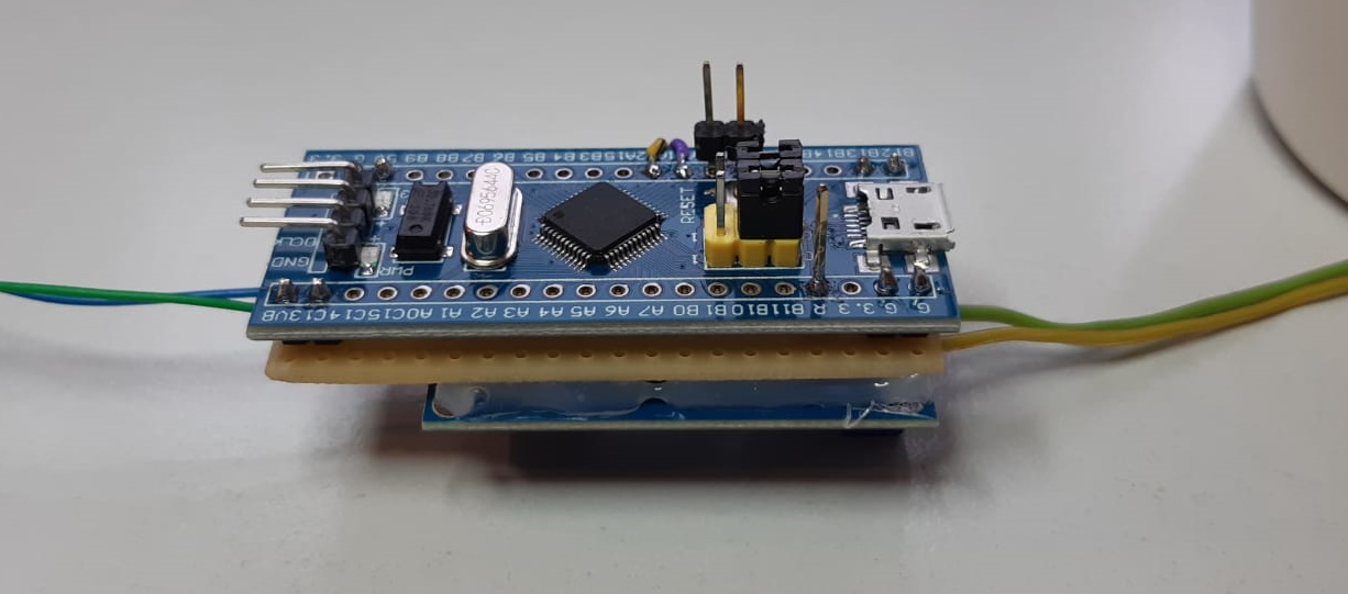
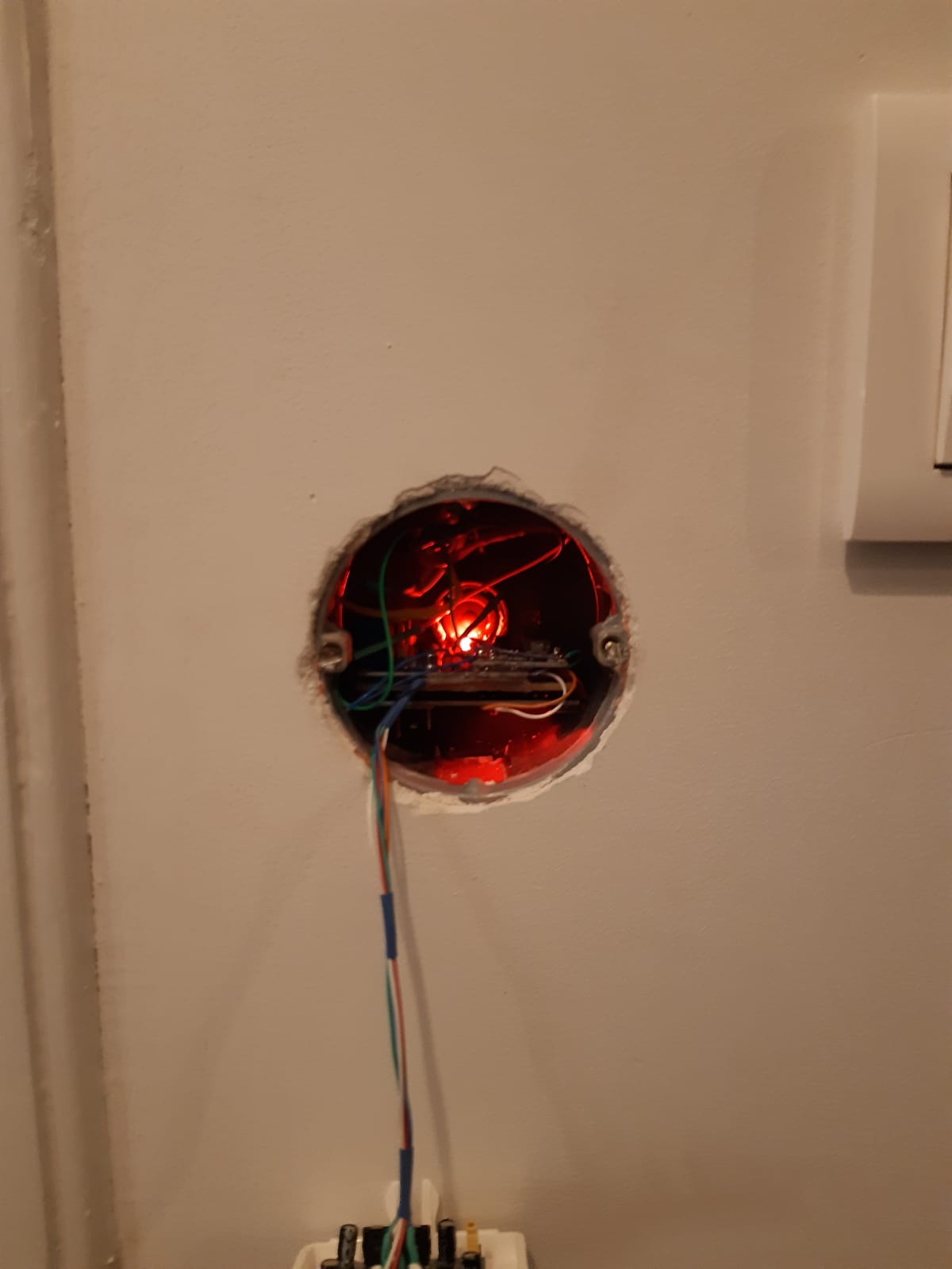
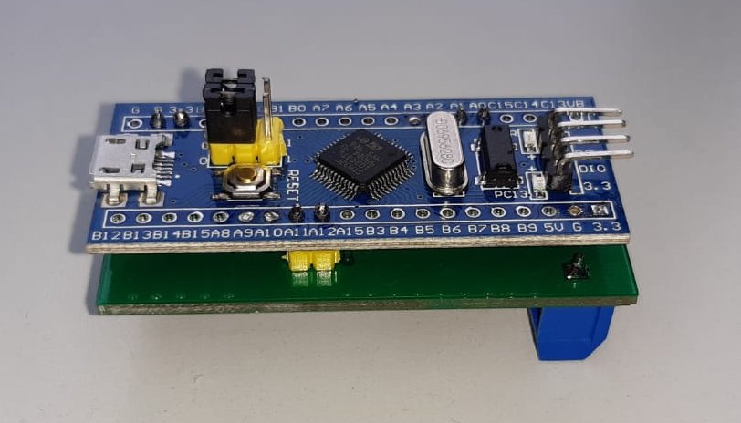
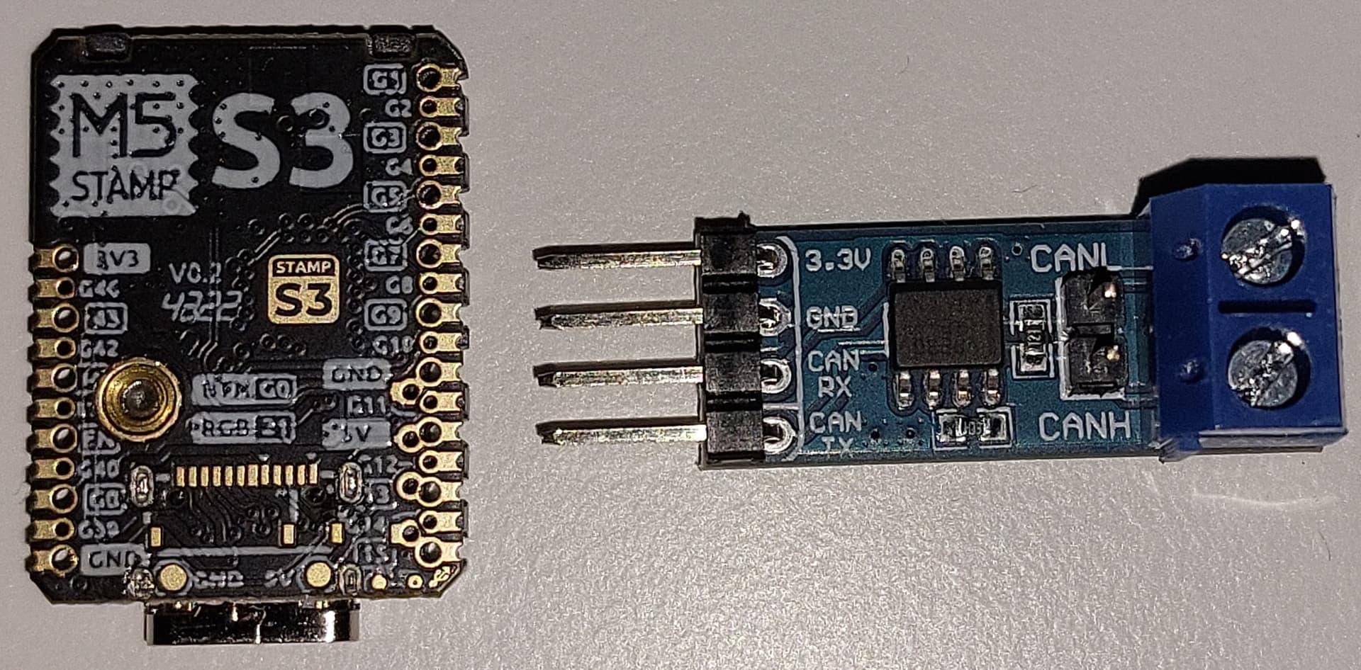
Proto hardware is up and running. Blue pill with a modified CAN driver board. The regulator will be replaced by a DC-DC upcomming days. This one runs hot.
Will add the motion sensor tonight. Everything still fits in power socket in the wall.
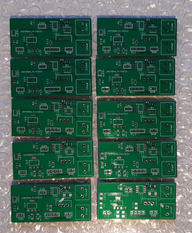
Most likely will make a custom PCB later on. Think I need about 5 of them around the house for motion detection. But this board can simulate any VelBus module if needed (and invested enough time to make it work).
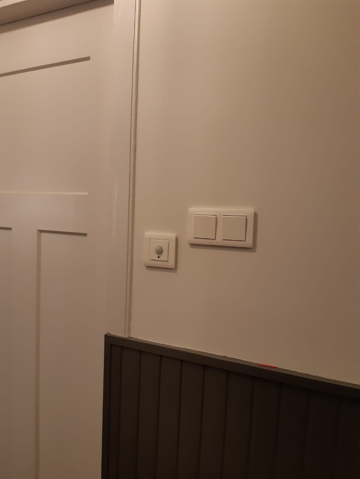
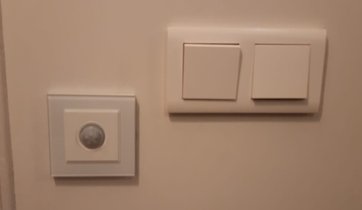
So things are looking pretty good. Used the same switch covers as used in the rest of the hallway.
Might be looking for some more fancy “glass” likes on aliexpress.
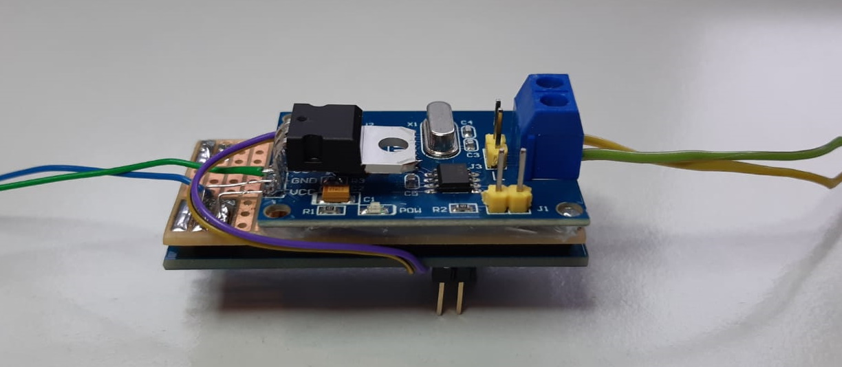
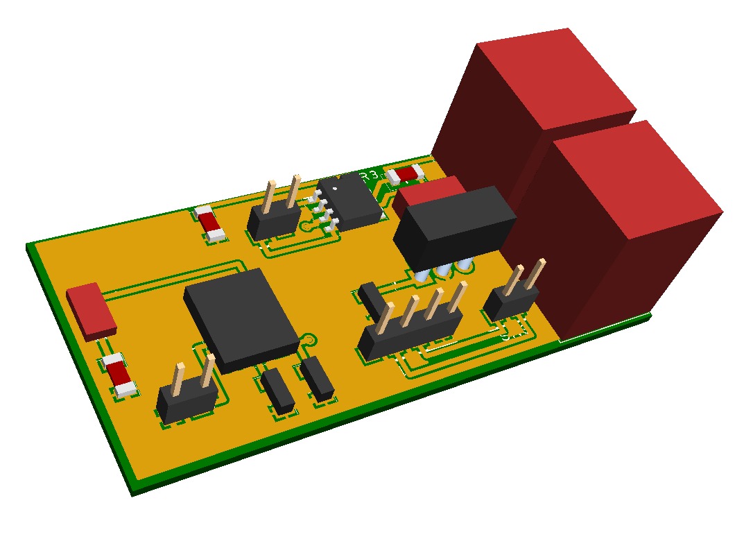
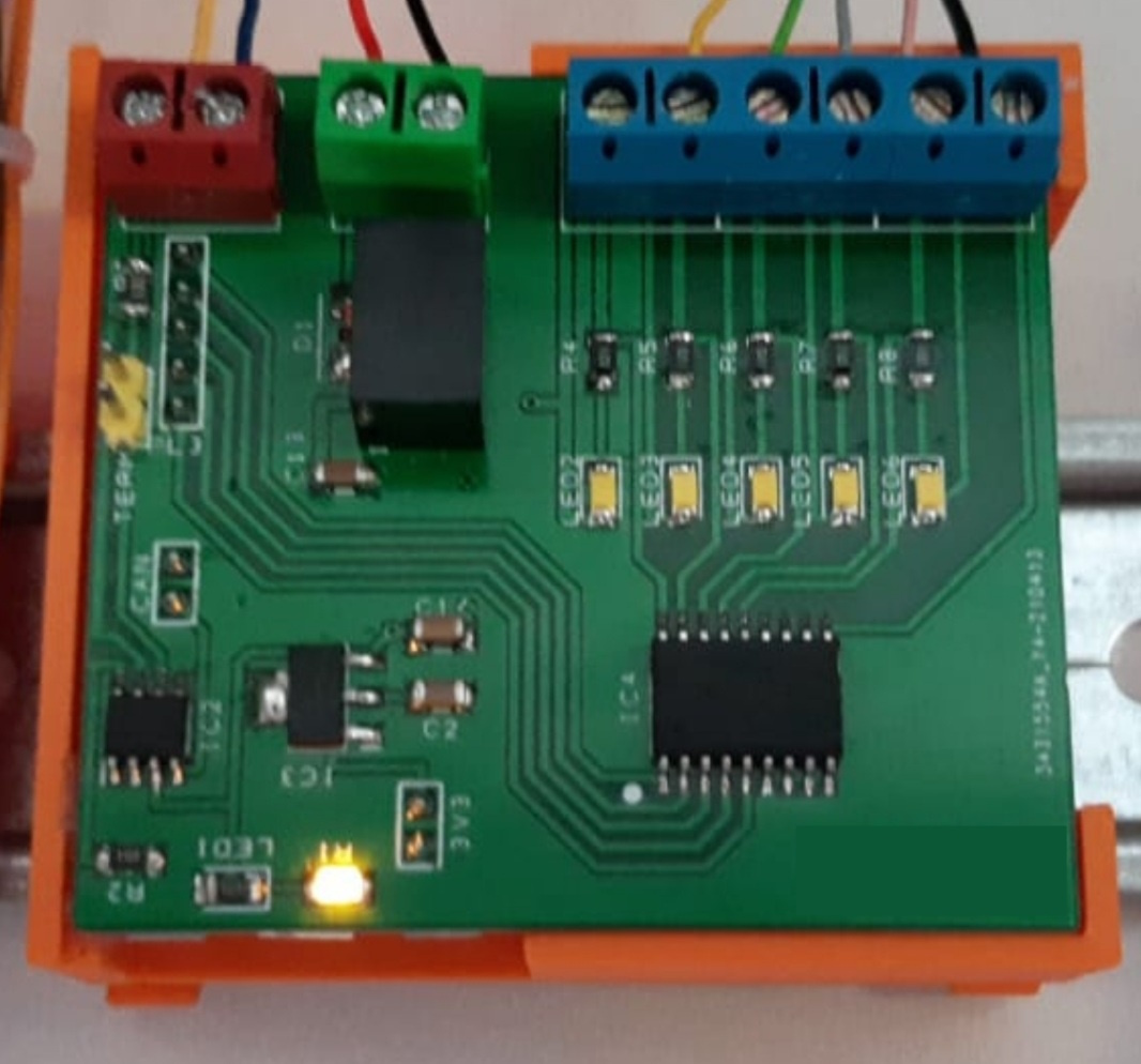
Also designed a PCB to reduce the wire mess on te back of the module. This makes it also easier to multiply the design.
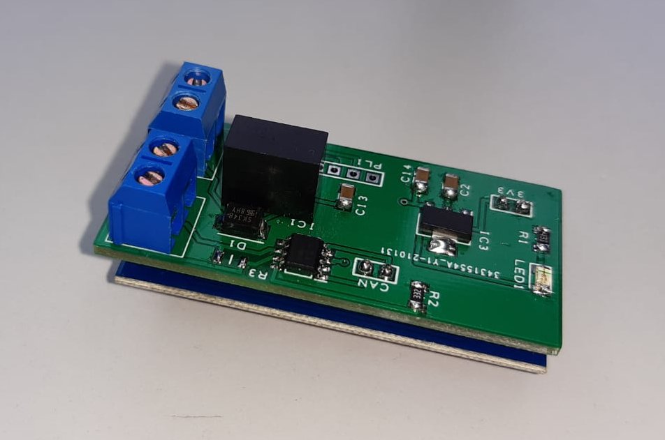
The STM32 board goes underneath this board. Kind of piggy bag board. Power supply from 15 VDC to 5 VDC (CAN & motion) and down to 3.3 V for the STM32. 2 red blocks are screw terminals for the 4 bus wires.
So the hardware is working and fits inside a junction box in the wall.
Bought a motion sensor with glass look on aliexpress. Removed the electronics and place the new module in there.
Now playing around with the software. Still some bugs to fix. Also I implemented only a limited set of features.
Want to use the same board (and software) to mimic an VMB8PB module too, so have to make some more changes to the software. That project will follow soon.
Currently have 4 DIY Velbus like modules operating in the house.
2x VMBPIRM (motion sensors)
1x VMB8PB (only single button to control the blinds)
1x VMB8PB analog version. A special version which can measure 2 analog inputs and compare those input values to 4 reference values to determine “above”, “in between”, “below”.
The UBS interface which I created is 99% compatible (must be some hidden features which I overlooked, so no 100%). But both VelBusLink and Velserv are happy with the interface and work perfectly with it.
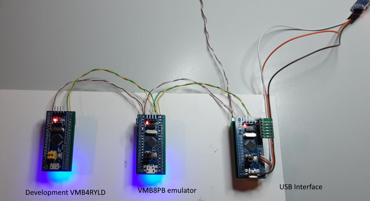
The VMB8PB emulator sends its status every few seconds. This is done to enable development of the other modules and have some triggers to respond to.
Plan is to start developing an “VMB4RYLD” output module. But as output modules contain the “rules” / “actions”, this module will be much more complex to emulate compared to the VMB8PB module.
But has been great fun so far and @Ggaljoen joined the team.
Ofcourse we will not be able to “clone” the original VelBus hardware 100%. But that is also not the purpose. Adding a few DIY modules to the existing genuine VelBus is enough. Meanwhile we are having great fun and learning a lot about STM32 too.
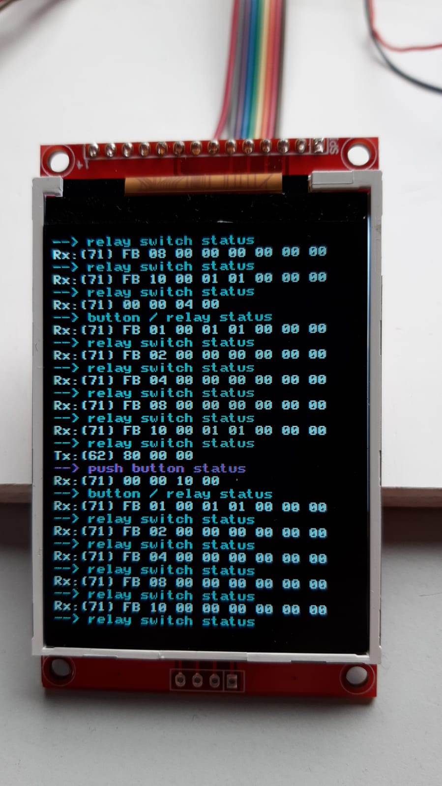
@Ggaljoen helped the project and made a logger which displays the CAN data on the bus onto an LCD screen. The screen is a “standard” arduino project which uses an STM32 too, and he added extensive logging to the velbus modules. Basically this logging is the same as the one found in VelBusLink, but then in hardware.
Logging is working so good, that Gert is going to make a dedicated logging VelBus module. Very handy when debugging the commands. And can be installed in the VelBus installation permanently.
This will definitely increase the “nerd” level of the VelBus system and impress my non-technical friends and make their heads explode. Just like the screens in the matrix movies.
@matthijsfh Fantastic work! Please post if you have any updates or anything you can share: code, PCB plans, documentation, etc. It would be a shame if it got lost! I’m gathering info if it’s possible to make a swimming pool chlorination and pump controller (*) (a few digital and analog signals) and looks like what you’ve done is perfect starting point
(*) controller might not be the best word - interface for monitoring and commanding the actual controller provided by the vendor of the system.
Not much progress. Most of my “modules with the same velbus interfaces” are working good enough to keep the wife happy
I did make a 5 channel output module. It has the basic behaviour of the VMB4RYLD, but only with the basic relay commands (no timers, no special stuff. On/Off/Follow and forced on/ off.)
Works well and saves me quite some money. The original modules are > 200 EUR each. So have a few official modules and now some DIY to get more IO on the bus.
Also finding the limits of the way I implemented the code. As I did not know how to start, my code is not optimal now things are getting very complicated. So the moment to call it a day is coming.
1 Thing on the list is to use the STM32F103 spare capacity better and have multiple Velbus modules running on a single STM32F103. “Only” 5 outputs is a waste of uP real estate.
Has anyone here actually managed to get ESP32 (V2 or 3) talking to velbus at 16.6 kBd?
I just ended up in some sort of Windows installer/IDE hell. VScode IDF components complaining that they didn’t have permissions to update or Arduino IDE libs not working at these low baud rates and cross compilation and python tools installed in very strange places so they don’t work from normal command lines and I cannot see how to set environment to use them directly.
I can see how to get the extra divide by 2 and modify an existing arduino lib but I can’t see how that is sufficient to get down as low as 12.5 kBd like the Espressif docs seem to suggest their SDK can manage. What has happened to arduino since ESP32 and MBED came along and they started wrapping everything? It used to be simple.
If anyone has an ESP32 simple example before I go crazy that would be great.
Alternatively I did manage to get Raspberry Pi Pico talking to Velbus fairly easily using Kevin OConnor’s can2040 driver (a software implementation of CAN2.0 good for up to 1MBd). That is fine but since the Pico Wifi has a ESP32 on board for the WiFi part that seems a bit unnecessary.
It is possible in the Arduino IDE to get it down to VelBus speed with the TWAI library, but a 1 digit change is required.
The file twai_types.h has a config for 16KBITS, the parameter “tseg_1” should not read 16 but 15.
What do you have in mind for the ESP32 (S2/S3/C3), a special use case in the make?
I see… so they push the bit-read right out to the end? With the extra /2 and BRP=62 and TSEG2 still 1, I make that maybe 16.7 KBd … which is probably close enough?
Which arduino CAN/TWAI library are you looking at?
The “arduino-CAN” library I found on github does not use twai_types.h; it just has a switch on the speed that sets the BTR1 and BTR0 register values but the settings for < 40kBd don’t work of course because the BRP ends up being more than 6 bits. It does not seem to to use the IDF driver support… just talks to the SJA1000 regs directly.
I have a few Wemos D1 Mini (ESP-WROOM-32 v3) on the shelf here and some older ESP-PICO-KIT development boards. I do not have anything in particular in mind yet… I just thought I would try a few different approaches (rPi-Pico, ESP32, STM32) for entertainment… to see which was simplest and most useful.
After messing around with painful Espressif and ST dev tools and VS-code all on Windows I think what I would most like to do is write a simple 8-bit AVR software driver instead :-/
Having ESP32 WiFi would be cool though… bound to be useful.
Oh… I was expecting Arduino libs… but you’re using the ESP-IDF headers in Arduino and then using the ESP-IDF driver?
I think the extra BRP divider started from ESP32 v2 hardware. I came across it in this old ESP32 forum post (in a 2021 post further down)
I have not looked at doing it with ESP-IDF directly. I thought there would be an Arduino lib that would be simpler… maybe even a lib that compatible with Arduino CAN support for Uno v4 and STM32.
I haven’t tried using ESP-IDF in Arduino. Thanks, I’ll go find an ESP-IDF TWAI example and take a look at what’s needed. I’ll pick up an ESP32S3 too, just in case
I can get the WROOM32 parts to work too as long as they are v2 or greater (my D1 Mini are v3.1). Its only the original 2016 WROOMs that have the old 1.0 chip version.
So I now have code running on Pi Pico, WROOM-32, ESP32-S2 and ESP32-S3, and STM32F103.
And have you seen Canable.io? All open source. It uses a newer STM part… STM32F042/F072, that is capable of running both USB and CAN at the same time (unlike the F103). There is a pretty cheap official ST Nucleo-F042K2 dev board but there are also adapters like this one…
It has no 16600 bd support out of the box but that is easily fixed.
I have a few very small CAN-AVR boards I might try out too.
Only thing I am missing now is the usual cheap MCP2515 boards on a.n.other MCU.
So lots of options to play with.
Still no idea what I will do with any of this yet but it’s interesting to play with.