Custom module problems in Home Assistant integration

I recently developed a custom Velbus module for controlling pumps and heating for my pool. I therefore mimic the VMB4AN module so I can transmit alarms and measured temperatures onto the Velbus. This all works fine up to VelbusLink which recognizes the module, reads the channel names and shows correct actual values of the sensors.

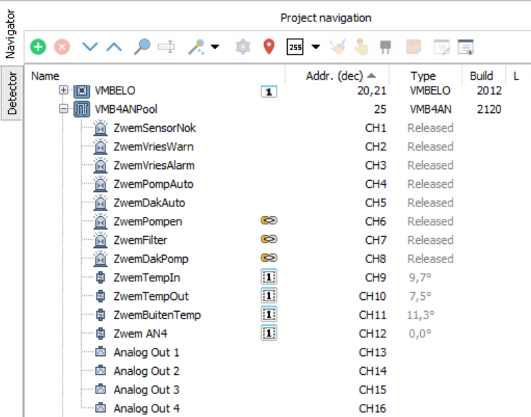
Correct channel names and sensor values in VelbusLink

However in Home Assistant integration I encounter following problems:

1e problem: Channel names and channel numbers seems mixed up. The VMB4AN protocol document defines channels 1 to 8 as the alarms, 9 to 12 as the sensors and finally 13 to 16 as analog outputs. I narrowed down a bit the problem to the identification off the channels in the channel name request (0xEF) and response (0xF0) messages. Where in most modules the channel Id is send by a 8-bit bitmask the VMB4AN identifies the channel by its actual number (1 to 16) or 255 for all channels in request message. The reason for this change seems obvious because the 16 channels could not be fitted into a 8 bit mask. Also memory map behaves different for additional channels …

Mixed up channel numbers / names in Home Assistant cache
{
“name”: “VMB4ANPool”,
“channels”: {
“1”: {
“name”: “Analog Out 1”,
“type”: “Sensor”
},
“2”: {
“name”: “Analog Out 2”,
“type”: “Sensor”
},
“3”: {
“name”: “Analog Out 3”,
“type”: “Sensor”
},
“4”: {
“name”: “Analog Out 4”,
“type”: “Sensor”
},
“5”: {
“name”: “ZwemDakAuto”,
“type”: “Sensor”
},
“6”: {
“name”: “ZwemPompen”,
“type”: “Sensor”
},
“7”: {
“name”: “ZwemFilter”,
“type”: “Sensor”
},
“8”: {
“name”: “ZwemDakPomp”,
“type”: “Sensor”
},
“9”: {
“name”: “Sensor 1”,
“type”: “SensorNumber”
},
“10”: {
“name”: “Sensor 2”,
“type”: “SensorNumber”
},
“11”: {
“name”: “Sensor 3”,
“type”: “SensorNumber”
},
“12”: {
“name”: “Sensor 4”,
“type”: “SensorNumber”
},
“96”: {
“name”: “SelectedProgram”,
“type”: “SelectedProgram”
}
}

2e problem: Sensor data is not updated (is handling of raw sensor data message 0xA9 implemented?)

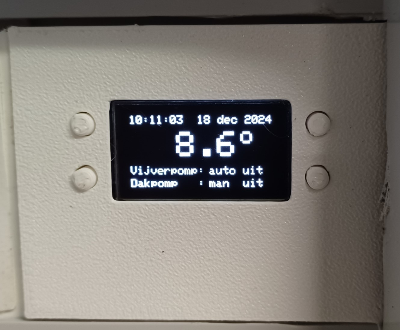
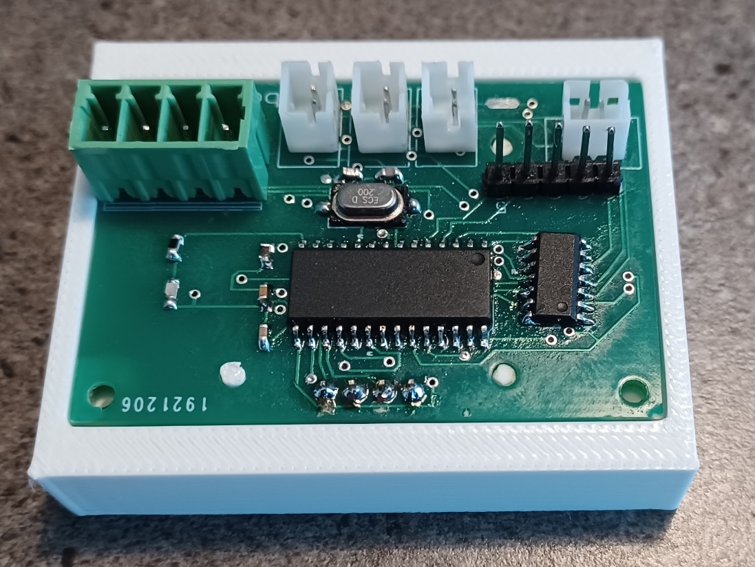
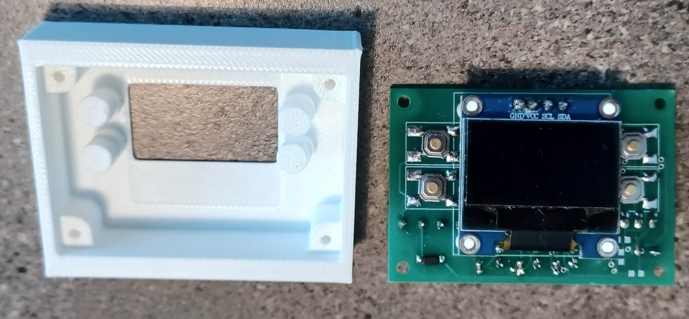
Some pictures of custom module


1 Like

Can I suggest that you pop a comment onto the GitHub repository for the Velbus integration in HomeAssistant?

Created issue on github … should have done this in the first place :stuck_out_tongue_winking_eye:

1 Like

This is interesting!

I like the 3D printed case with buttons, and the (SSD1306?) oled module.
Please tell us more about your approach with the hardware?
I would ask more about the HomeAssistant side but I don’t use or know much about HA so would not know where to start (I keep meaning to make time to take a closer look at it but it hasn’t happened yet).

3D printing is just another hobby that comes in handy … and the oled module is indeed the very cheap SSD1306.
My hardware approach … I developed some standard hardware / software design around the microchip PIC24 family. Often I mimic multiple velbus modules within one hardware module and add some custom functionality.

Some examples:

  • showed vmb4an: looks like a normal vmb4an from velbus side but has some custom logic for pool pump control
  • vmb4dc dimmer: normal vmb4dc + actual cut off dimmer hardware
  • vmb4_16A: normal vmb4ld (16A relay output) + vmb8pb (8 pushbutton module)

1 Like

You made all those boards! That’s awesome. Nice work.
Interesting choice of PIC24… I used PIC12/16/18 a long time ago but never really looked at PIC24 closely.

I am particularly interested to see that you went to the trouble of emulating exiting Velbus devices so your hardware works with Velbuslink. User matthijsfh did something similar with STM32 a while ago… Thread was here…

https://forum.velbus.eu/t/building-custom-velbus-devices

I had a play with getting several different breadboarded devices monitoring and driving Velbus directly but I guess I never found the right application to take any of it any further. Plus I have to admit I am not very good at finishing things. I thought at the time that emulating existing devices looked like a lot of work though. How much of the vmb4an and vmb4dc commands and responses did you need to replicate to get Velbuslink to work with your hardware? Was it a lot of work?

My setup here is all pretty standard Velbus. Only enhanced bits are a Pi-3 to run velbus-tcp-snap so I can connect over the network and to act as RTC; and a VMB8PBU wired to an arduino UNO as a universal RF-remote receiver.

Thanks for the photos and info. Nice to see another hardware geek in here… Makes me want to have another go… both at the hardware, and at HomeAssistant.

1 Like

The first board is the hardest … once you got one working, next one is a lot easier.
Choice of the PIC24 is just a matter of personal experience. To be honest, if you are starting from scratch the STM32 might be the better choice.

Staying compatible with Velbus was, and will always be, the main goal. Velbus is just a lot more then some custom modules. I only build custom modules when there is an actual added value and I also have lots of native Velbus modules. (fe I really like the glas panel modules !)

I covered in my custom modules most of vmb4dc and vmb4ryld modules with added output hardware (AC / DC, solid-state, mosfet dimmers …). I also have vmbbls for blinds and VMB8PBU for PIR and radar detections. Recently I started a new development with the VMB4AN where I only cover alarms and basic sensor readout for Velbus but add functionality for pool control (I needed some analog computations for pump control, freeze garding, sun based heating … and local control with oled display)

If you would go for PIC24 and like C language … a look at the velbus PI hat project might interest you: https://forum.velbus.eu/t/your-post-in-velbus-interface-raspberry-pi-4-hat/17423

Good luck

1 Like

Nice work. I should get back onto my custom modules for the switch inputs I was working on. But then got distracted by installing solar panels on my house, and on my garage :slight_smile: I’ve almost finished that project (summer here so getting lots of free power).
I was using the Renases RA4M1 chip, the one in the new Arduino Uno as it has a built in CAN controller so only needs a transceiver. It also has ample RAM, flash memory and emulated EEPROM for storing configuration data.