Not sure if this is the right forum for this - but I guess it would be …
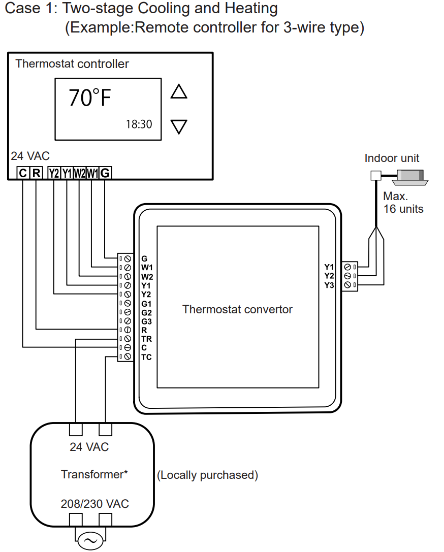
I am trying to figure out the wiring for my new AC unit. Which has a “generic thermostat aux module”. This module exposes the standard connections to link up a thermostat (like Nest). Y1, Y2, W1, W2, G1, G2, G3 etc…
the question is now, how a “regular” thermostat would switch these… and Y1, and Y2 to be switched in AND mode
Y1 + Y2 == boost
or exclusive mode (OR)
Y2 == boost – Y1 == OFF
This as the Velbus thermostat kicks in the heater + booster channel for “booster mode”
And would the same principle apply to G1, G2, G3?
G1 AND G2 AND G3 == Full speed
versus
G3 ==Full speed
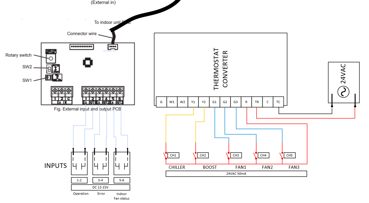
This is in the manual - I think I found it out… essentially I have to short the R to the Y1/Y2/etc… the manual states either to link the G or use the individual fan speeds on G1, G2, G3… which is my plan
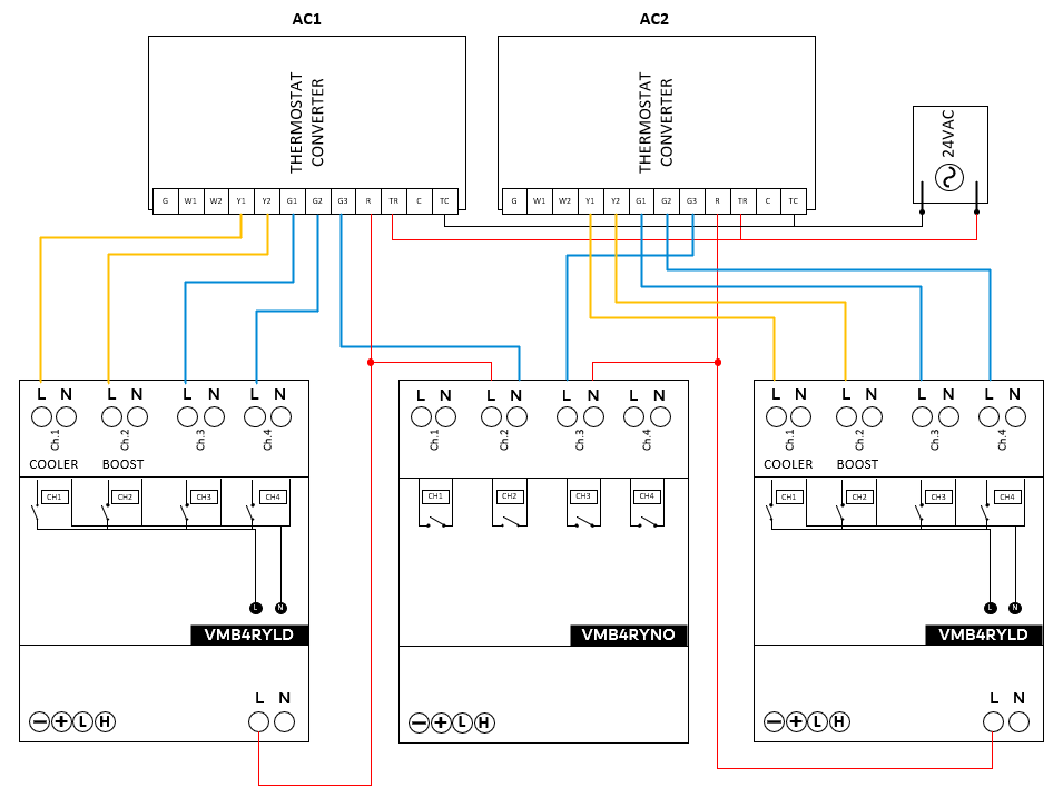
This is my proposed design - to drive the control for 2 AC’s
yeah… its a labeling thing… the middle one is a RYNO…
And I probably will configure it like
4 alarms (mode’s for the thermostat)
1 = X = Off
2 = I = on demand compressor (Y1) / fan G1 (low speed)
3 = II = on demand compressor (Y1) / always fan G1 (low speed)
4 = III = on demand compressor (Y1) / always fan G2 (medium speed)
Booster channel (Y2) relay + fan (G3) high speed
but if the fan needs to go high-speed - I need to force the medium/low speed fans to off (to prevent mixed signals) - I’ll probably use the “Forced off when initiator closed” for that
After some feedback from a very knowledgeable man… I configured the AC to:
Alarm 1 == Day (II) or Comfort (III) mode
Alarm 2 == in Night (I) mode
Alarm 3 == if set temp + offset < +3C
Alarm 4 == if set temp + offset < +5C
And I’ve configured the channels as:
Cooling ==
Y1 follow
G1 on when initiator closes, delayed off when initiator opens + 1 minute
Boost
Y1 forced off while initiator is closed
Y2 follow
Then on the alarm channels I’ve put
1 == nothing
2 == enable Silent Mode (an option on the roof unit to make less noise)
3 ==
G1 forced off while initiator is closed
G2 on while initiator is closed
G3 forced off while initiator is closed
SM mode forced off while initiator is closed
4 ==
G1 forced off while initiator is closed
G2 forced off while initiator is closed
G3 on while initiator is closed
SM mode forced off while initiator is closed
That way the fan should go into medium (3) and full (4) upon those items… - and the silent mode can be disabled in this case (to get more power from the unit) - while on normal nights we have a pre-set temperature + silent mode and during the day - normal operation and day temperature…
Now my feedback to @velbus is - can we please replace the icons on the thermostats for the cooling mode of the thermostat. having fan blades representing day/night mode is a bit silly - as they might not represent the actual usage of the fan or the set temperature compared to the fan speed…
okay… back to the design board… it seems the booster channel only kicks in for the heater… not the cooler… - guess I’ll add it to alarm 4… or something
 …
…