I have a working installation, all modules were correctly found by Velbuslink. Programmation is done and working as well.
However, today, when I logged in the VelbusLink, I noticed that 5 relay modules were not found (the red cross icon), even after having clicked on “Scan”.
The strange thing is that the modules still work in the installation (I can still turn on and off the plugs connected to the relay module). And strange enough as well, the column “type” in the VelbusLink, in which we can see the status of the different channels still display the correct information (“on” if it’s turned “on”, and “off” if it’s turned “off”).
But as the modules are not found, I cannot change the configuration anymore.
Does anyone know what is the problem for that?
(I tried to connect with the USB cable and with the HomeCenter… same result).
Could you check the troubleshooting chapter at the end of the “Velbus Installation Guide: Part 2 Configuration” please? Follow the relevant steps there and let us know what happened.
(Download link on https://www.velbus.eu/, sidebar, and on the product pages).
I checked and there was indeed a power cable which was still but incorrectly connected in a module. The strange thing is that I did not touch the installation (physically).
It seems my installation is not properly done.
It’s fixed now, thank you for your help.
Just because it might help someone in the future a lot of troubleshooting…
My VMB2PBN was undetected. This has worked in the past.
The cable was connected to the bus of a relay module. After measuring the voltage on the button side was only 2.8V (which had no leds on and took me a bit to figure out where to find it and how it’s supposed to look like). After wiggling with some of the wires I noticed one was loose and after refastening it again the button got the leds functioning and the button was found during a scan.
I had a similar issue for other modules but wiggling the cables “resolved” that.
What would be the proper way to manage these little wires? I found a little module for that but it seems that it’s no longer being produced?
It worked before, I reseated the cable properly, it works again. All modules to be clear. Not trying to be a wise-ass
I’m trying to understand how the installation would work if there was a termination issue. Wouldn’t it either work or won’t work (partially at least)?
I marked the place. One of the red wires.
That looks like CAT5 cable, which isn’t perfect for Velbus due it it’s small size.
It’ll work perfectly well, but does cause small issues like this when not used with ferrules or the VMBRAIL
Thankfully, Velbus V2 hardware now uses Molex 4-pole connectors and an easier to terminate Pheonix connector block.
The best thing to do with your installation is to pop all those CAT5 cores into a ferrule and gently grimp them together, before putting them into the rising cage of the modules.
But be careful not to apply too much pressure, as CAT5 cores can fracture really easily.
Have a look at this CANbus fault finding interactive PPTx presentation, that loads in a web browser or can be downloaded.
If… a CANbus cable is damaged or a single core connection fails, as long as none of the cores are shorted, what should happen is that you ONLY lose functionality of any downstream modules.
Unless there is a loop in place, in which case you wouldn’t notice until a second fault appeared.
I actually thought about soldering them together since it’s just too many small wires coming together in that hole.
Would work but is less practical in case of troubleshooting.
In fact, Velbus starting fitting these as standard on wire ended modules (like the old VMB8PBU).
Everyone doing this stuff should have a batch of mixed ferrules and a crimping tool handy anyway… they are useful for all sorts of stuff. The bigger ones are handy almost everywhere that you use stranded cable.
There are also “double” ferrules that are handy for general distribution-board wiring on the AC mains side. If you use single insulated stranded hook-up then a quick twist of the stripped cable end and then pick a ferrule size such that the insulation pushes inside the collar… result is all neat and tidy with strain relief built-in.
Handy mixed pack…
And because I do use CAT5/5E everywhere (though there are reasons not to, as MDAR says) I keep an extra large supply of the white 0.5mm ones, and the double-ones of the same, like here…
Some of my old-style Velbus with extensive use of bootlace ferrules.
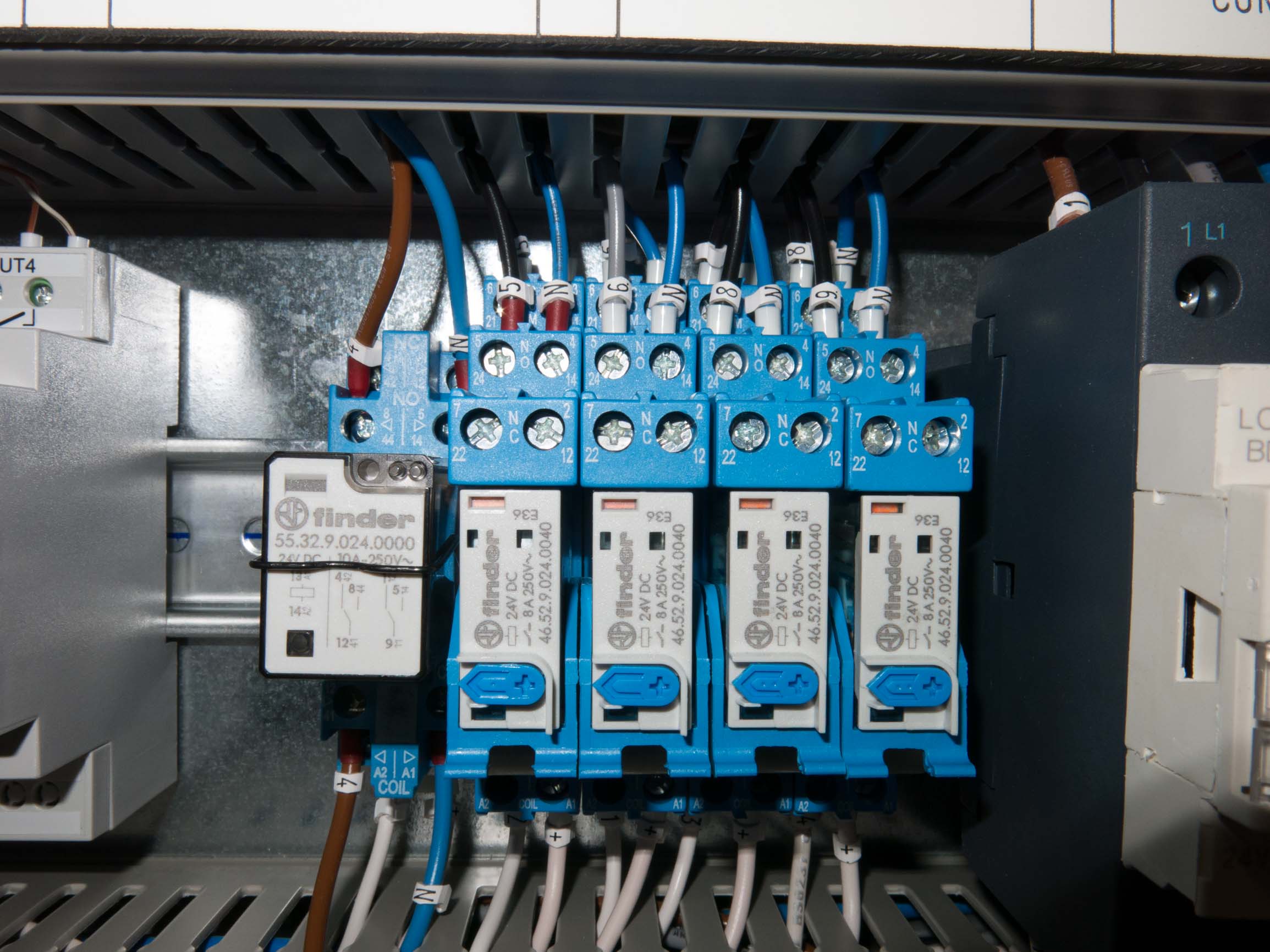
It is not obvious here from this angle but the chained switched common (240V AC) connections on that VMB4RLYNO (bottom right, short brown wires, grey ferrules) are double (Y shape) so that insulation of both wires fits down inside the collar.
You can get quite fast at doing everything this way with a bit of practice.