Hi,
i have installed a dimmer to control a dimable led that is sitting in a multi light chandelier. The chandelier has unfortunately only 1 cable for common for all its light points. So i am thinking to connect the dimmer channel (to control the dimmed light point) and 1 more on/off typical channel of VMB4RYLD (to control another light point in the chandelier)using the single common cable of the chandelier. Is that a problem for the dimmer?
Also the dimmer fuse is difficult to understand if it is placed correctly and makes contact inside the casing. Any advice on how to know if the fuse is making contact correctly when rotating it (putting it in and rotating) ? As there is no block point to the rotation of the fuse cap, you dont know if the contacts are in the correct place or not as you turn the fuse while inserting it in the base of the fuse.
Hi
I’m a little confused.
What are you asking?
If your chandelier only has 1 supply cable, containing a live, neutral & earth, then that is only 1 circuit.
So you can only control it from one device.
However, if it has
2 x live
1 x neutral
1 x earth
Then you could in theory share the neutral between two circuits so that you can operate them independently.
If you only have 1 circuit to the chandelier, then your only option for separate control will be some kind of “smart lamp”.
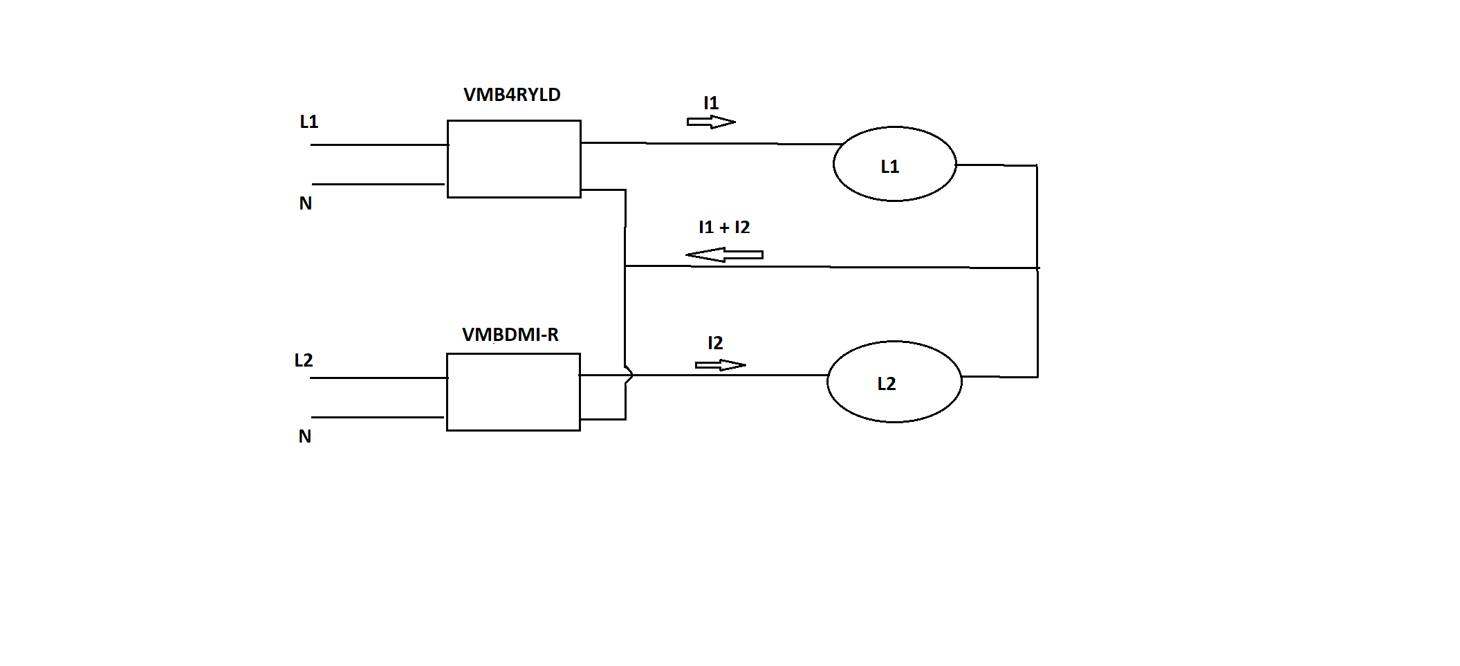
The chandelier has indeed 2 live, 1 neutral and 1 earth. And my question was, is it ok to share the 1x neutral between a dimmer module and a generic on off module to control the 2 lives ones independently?
In theory i know its ok, but i am not sure if you do any kind of differential current monitoring or anything else that could be confused by sharing the neutral line with another installation.
Let me add a figure here.
Kind regards
Hi
Yes, that’s absolutely fine 
The VMBDMI-R doesn’t do anything with the Neutral line, other than user it for reference.
What you’ve drawn there will work perfectly
Regarding the bigger picture of current monitoring etc, don’t forget that it’s all done on the live side anyway and the Neutral is (most commonly) connected directly to the earth on the other side of your electricity meter anyway. (Known as PME in the UK)
The only issue with sharing the Neutral across circuits is if you are foolishness enough to bridge between protected circuits, especially when you have RCBOs, but that is WAY beyond what you’re suggesting here.
As long as you’re only referring to single complete fixtures, which share the neutral, you’ll be absolutely fine.
Can you post a video of it all working, so others see what you’ve achieved.
Good luck,
Stuart
Had to replace my dimmer modules with newer versions, after that all worked ok. I now can control the on-off and also the dimmer spotlight using the diagram above.
Oh okay…
Not sure why changing the dimmer made an difference, unless it was doing something with the Neutral line, but I’m glad that you have it all working now 
Yea, i also dont get why the newer versions would work and the older one had issues. I am not aware of the internal architecture of the dimmer so i cannot make any assumptions. Overall, those dimming modules seem to be very sensitive and troublesome while the rest of the hardware i used from Velbus is quite robust. I had to change both of them i had installed initially until the later ones are working as intended (so far at least).