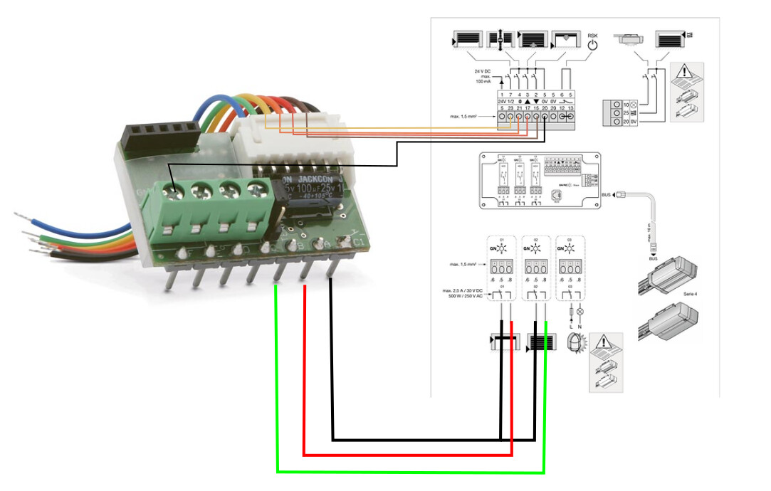
We have recently placed a Hormann garage door with a Promatic 4 engine and the seller advised us a UAP1-HCP adapter to be able to make the connection with any smart home automation system. Sadly they don’t know how to wire this with the right Velbus modules so im looking for help on the forum.
I have a VMB4RYNO relay which is now directly connected to the door engine but this only sends a pulse to open or close the door. It does not read any open/closed status or whatsoever. I assume that i need to connect the velbus bus cable (4 wires - red/black/white/yellow) from the bus to this UAP adapter somewhere. And what about the 2 cables from the relay?
I happen to have a VMB6PBN that is connected to VMBRAIL-R which is connects the rest of the velbus installation together. With the VMB6PBN i currently switch on some lights. From the velbus installation theres 2 power cables (red/black) that currently run from a VMB4RYNO relay straight to the Promatic 4 engine. I use the VMB6PBN top left button to send a pulse to the engine which opens the door and if i press the button again i send another pulse that stops the door. Pressing a 3rd time finally closes the garage door.
If you would have a wiring diagram of how to connect the specific output contacts from the door system to the right inputs of the VMB6PBN or the VMBRAIL-R, ill give it a go.
For now i dont dare to touch it because im afraid that ill short circuit things which is a bit costly
I dont mind waiting until you are back from holiday, take your time and enjoy!
Yes it is working but i have no control over the direction of the door.
I receive no feedback from the door system as you say, so if im not at home and i press the button to send a pulse, ive no idea what direction the door is going.
There is no possibility to open the door, pauze the door, and go back to opening. Its always going back to the opposite direction for now.
Oh, interesting! I will be watching this thread.
My garage has two Hormann Promatic 4 doors. I as not aware of the UAP1-HCP adapter module… is this standard or an optional extra?
I also have Velbus available in the garage but I haven’t done anything with it yet apart from the light switches as I did not think I had a need/application for the doors.
Are you wanting to connect the doors to Velbus “just because you can” or do you have a specific application in mind?
Not that I NEED to have a good excuse to justify this to my wife… but it might help
ive no idea what direction the door is going <…> There is no possibility to open the door, pauze the door, and go back to opening. Its always going back to the opposite direction for now.
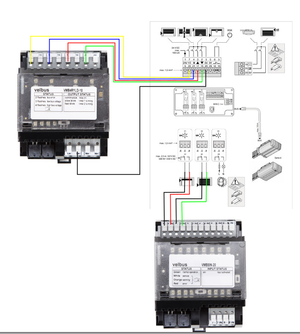
Whether the door is in motion is probably best determined with some sort of a timer. The blind relay (BLE) modules have a timer built-in, and you could connect the UP/DOWN channels to the contacts 17 and 15 to specifically have a control of directionality. Read the spec to see if those allow for continuous signal, rather than a pulsed one.
I receive no feedback from the door system as you say, so if im not at home and i press the button to send a pulse…
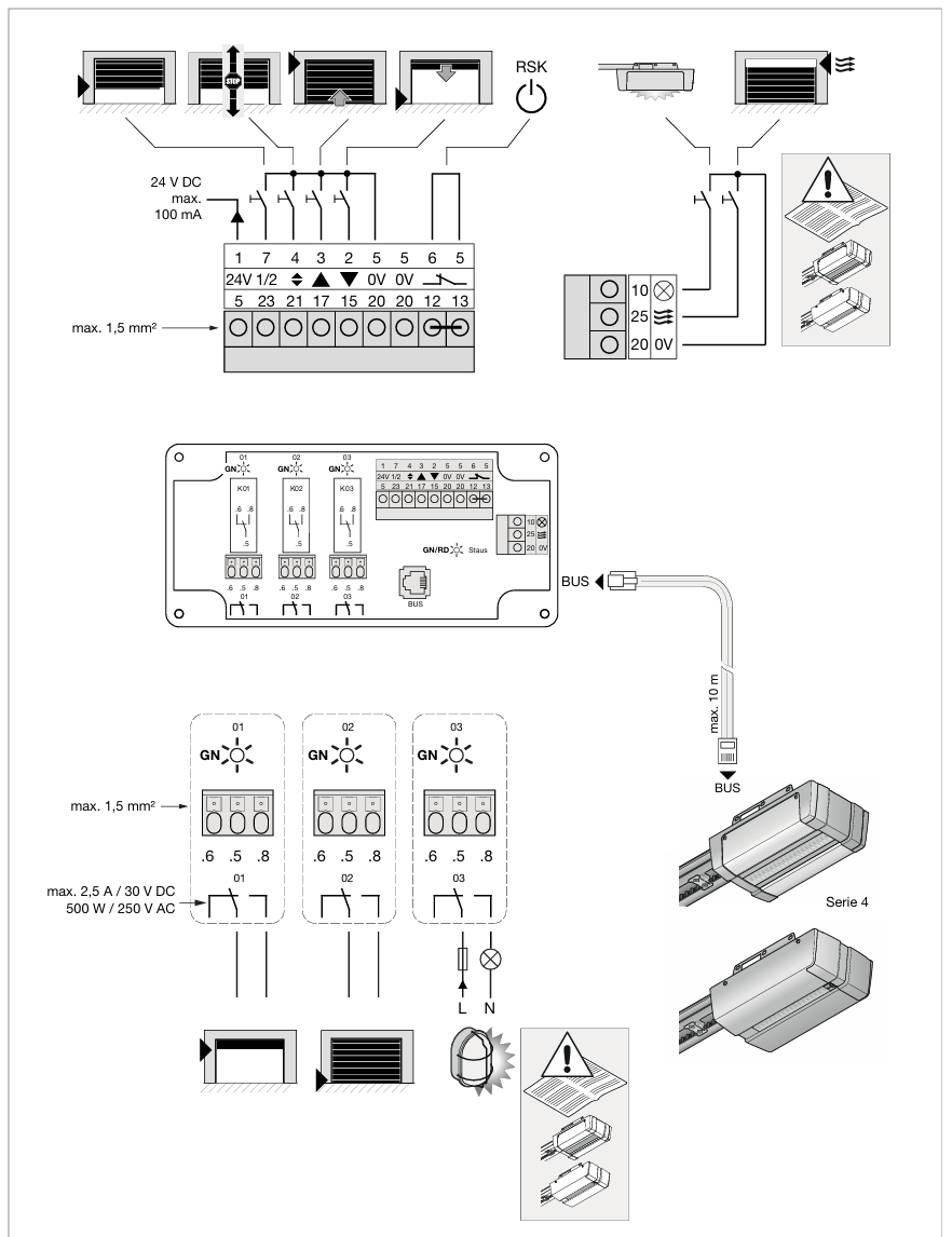
From the looks of it, the GN01 and GN02 dry contacts describe whether the door is fully open or fully closed. So you would need a VMB8IN-20 to detect that state (or if you’re cheap, you could build something with an ESP board and some ESP Home), wiring common to the .6 contact and one of the inputs to I presume the .5. From there you would likely get 2 bits of information:
GN01 closed GN02 closed – shouldn’t be possible (or you wired your feedbacks in reverse)
GN01 closed GN02 open – door is fully open;
GN01 open GN02 closed – door is fully closed;
GN01 open GN02 open – door is neither open nor closed, but also not necessarily in motion (see the note above about a timer to determine if the door might be in motion.)
Though to be honest having a camera pointed at the garage door would be more fail-proof (the motors also use heuristics to determine if things are fully open or closed) and double as some additional security for your garage door…
are you shure you’ve connected your relays (or 2 switches) between 5/3 (closing) and 5/2 (opening)? The behaivior you’ve described is possible when you’ve connected your contact between 5/4.
I’ve noticed that the uap1 is upgraded slightly to my version. With my version the behaivior of the switches is as follows:
one push open: the door opens, pushing the switch “close”, the door stops
one push close: the door closes, pushing the switch “open”, the door stops
When closing the door, there’s always a chance something comes in between the door, the door than stops and opens again. This is always something to keep in mind (also when using the remote) so feedback is a must if you can’t wait .
@EvAndy , I use my control of the door to open up the door through my cellphone. i’ve created buttons on a tab to open and close it. I only have one remote and my cellphone is always nearby (ex. in the holder in my car). Probably it can be possible to create a link with android in cars, but since I’ve got an older car … Second use is to have some open/close buttons a different switches in my house so I don’t have to go to the garage to open up the door when the childeren forgot there key. Note that I don’t have a keypad to open up the door, maybe in the future when my kids are a bit older.
Also interesting to implement: when opening the door through the cellphone, cretae an autoclose puls after ex. 1 minute. It could happen that the port is activated by coincidence, just damage control
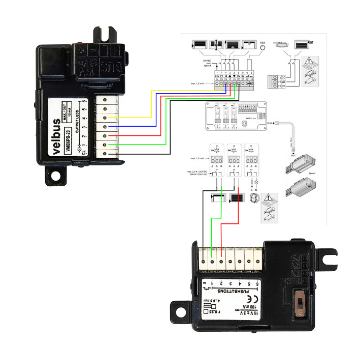
Using an VMB6PBN, with a strict change to the configuration.
Where the LED outputs are used as 0V triggers. NOTE WHERE THE 0V for the pulses is connected on the VMB6PBN
This is done by Setting them to Monitoring Mode and attaching 0104 actions between the LED outputs and the Velbus buttons that you want to control them.
(I have been doing this with Velux KLF200 controllers for years, and ASKING for a Velbus IO device for the same time, for exactly these situations)